 It
It En
En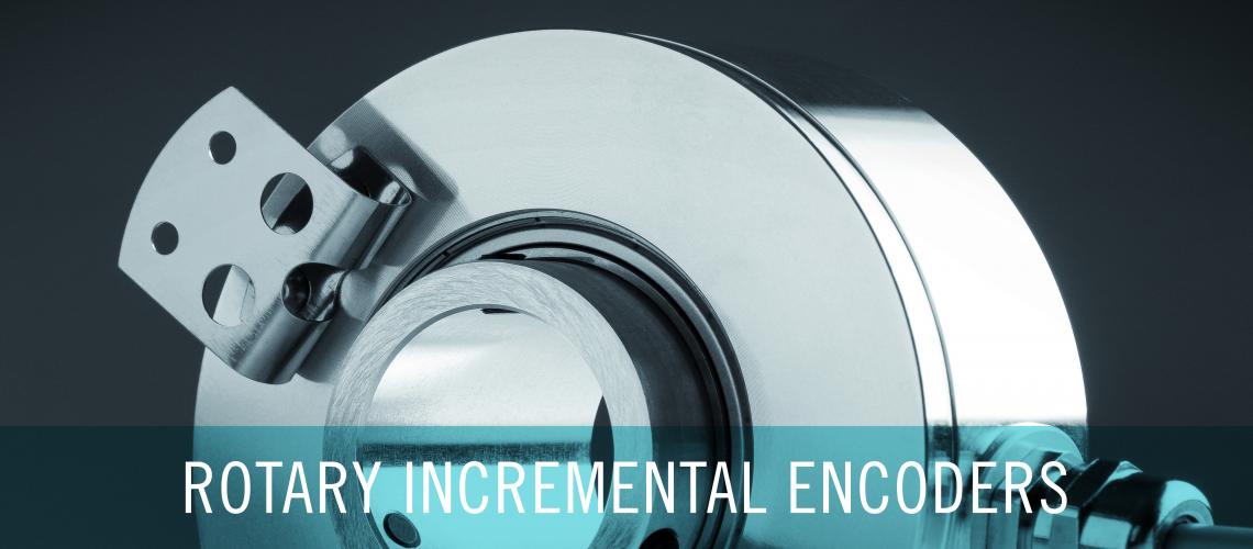


Categorie prodotti
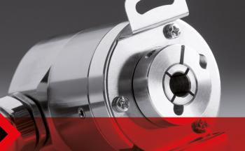
Encoder rotativi incrementaliLinee di encoder rotativi incrementali ad albero sporgente, cieco e passante
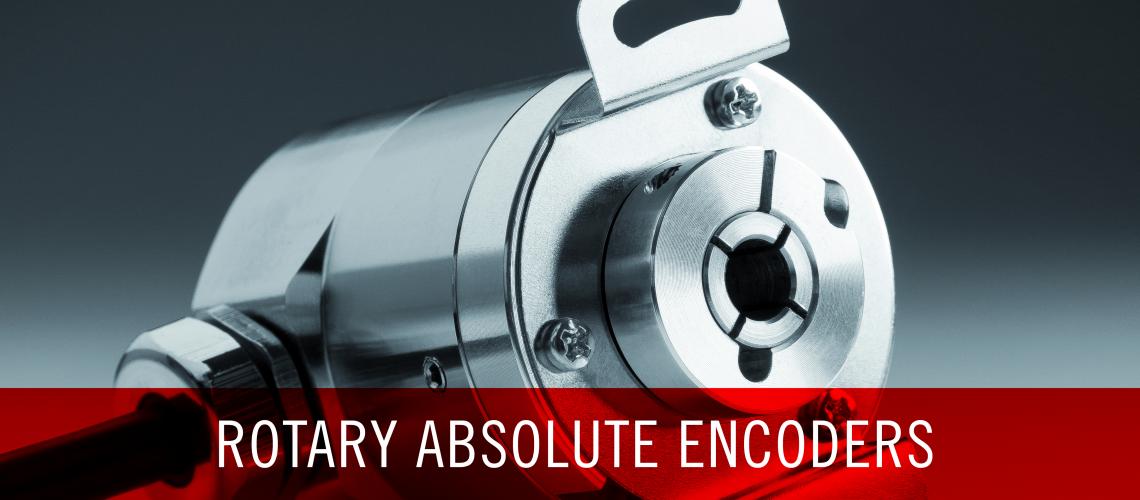
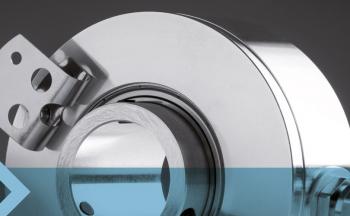
Encoder rotativi assolutiLinee di encoder rotativi assoluti mono e multigiro Eltra
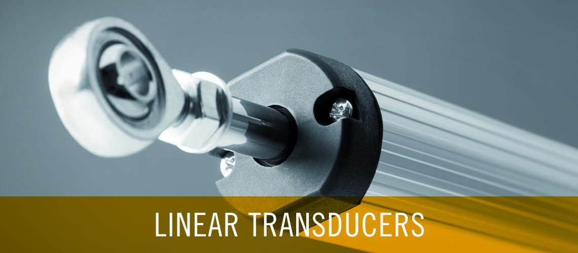
Trasduttori LineariLinee Eltra di encoder lineari, potenziometri e magnetostrittivi
Altri prodotti
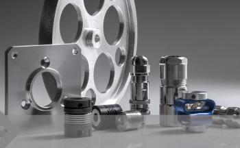
Accessori
Applicazioni
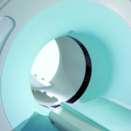
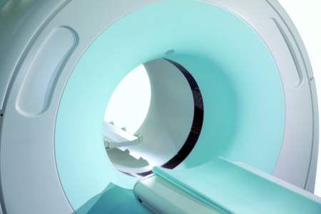
Tecnologia medicale
Linee di massima accuratezza e precisione per garantire un controllo ottimale delle ultime tecnologie in ambito medico-scientifico.
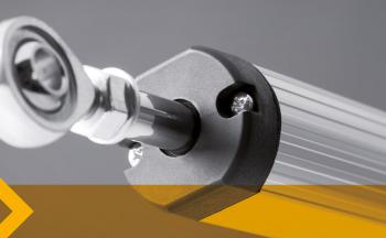
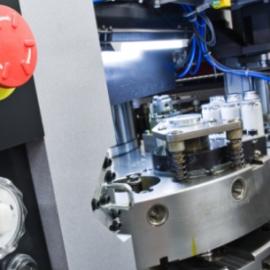
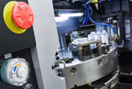
Motion control
Soluzioni con elevato grado IP, estremamente versatili e semplici da assemblare, particolarmente adatte al controllo di movimento.
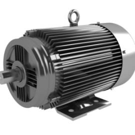
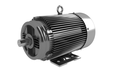
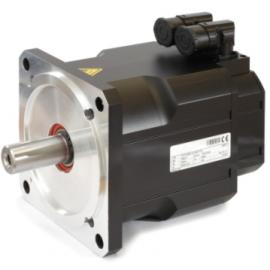
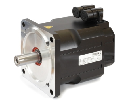
Motori sincroni/asincroni
Gamme di encoder ottici e magnetici, resistenti ad un ampio spettro di temperature e ad alte velocità di rotazione.
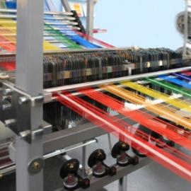
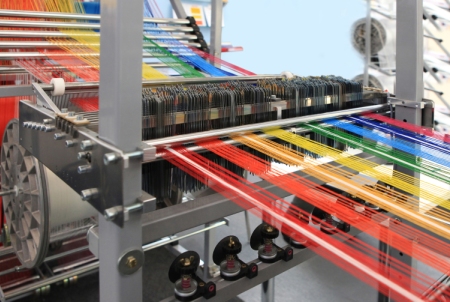
Industria tessile
Soluzioni particolarmente solide e resistenti a vibrazioni e polveri, che garantiscono al tempo stesso velocità e risoluzione elevate.
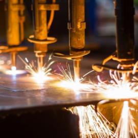
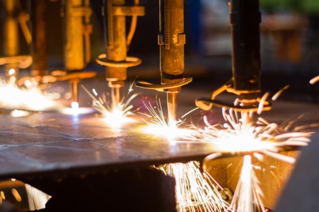
Metalli
Gamme di encoder assoluti ed incrementali ad alta resistenza meccanica, idonei per il processo di metalli ad alte temperature.
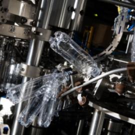
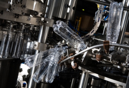
Industria alimentare
Gamme di encoder in acciaio INOX, con alto grado di protezione IP per proteggere il dispositivo da prodotti chimici e liquidi e garantirne la massima affidabilità.
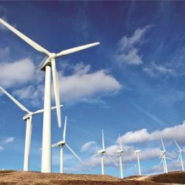
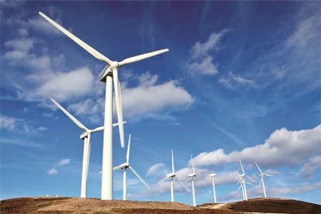
Energia eolica
Soluzioni resistenti ad un ampio range di temperature e a condizioni estreme per l’ottimizzazione dei sistemi Pitch e Yaw nei generatori eolici.
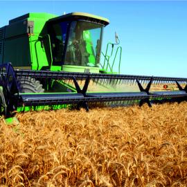
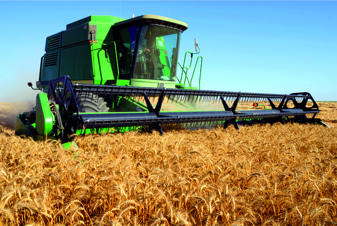
Macchine agricole
Gamme ad alta precisione e semplici da montare, studiate per la rilevazione di misure lineari di lunghe distanze.
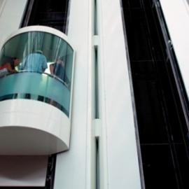
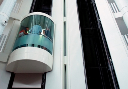
Ascensori
Linee di encoder rotativi incrementali ad elevata risoluzione e precisione studiati per garantire la massima affidabilità e sicurezza.

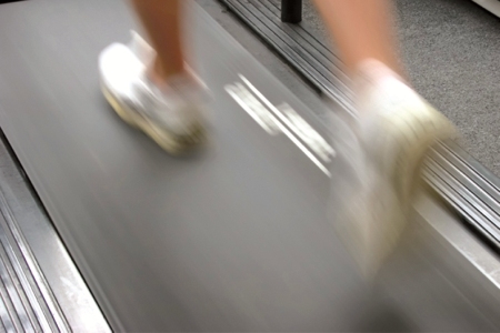
Event technology
Gamme di encoder rotativi e lineari progettati per macchine per fitness, strutture automatizzate di teatri e giostre meccaniche.
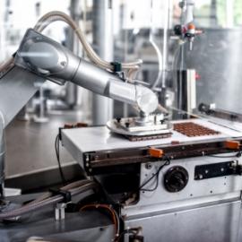
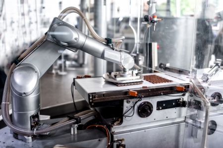
Robotica
Encoder ad alta risoluzione ed elevata frequenza operativa per assicurare la massima precisione di sistemi automatizzati e robot industriali.
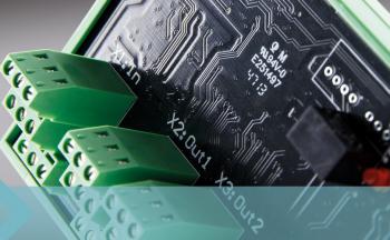
Motori brushless
Dispositivi compatti con fasi a effetto Hall, ad alta resistenza meccanica, con un’ampia scelta di risoluzioni e di interfacce elettroniche.
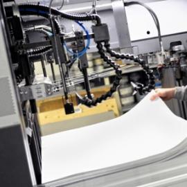
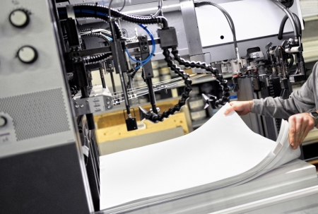
Carta e stampa
Gamme di encoder ad elevato grado di protezione IP, resistenti ad acqua, umidità prodotte nella lavorazione della polpa.
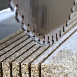
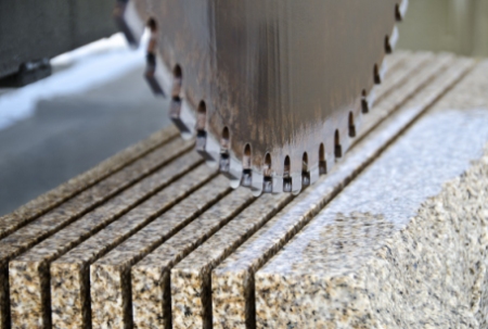
Pietra e marmo
Soluzioni robuste ad alta risoluzione e precisione, progettati per la lavorazione di marmi, graniti e pietre.
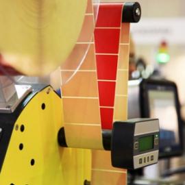
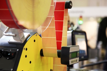
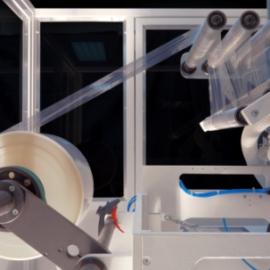
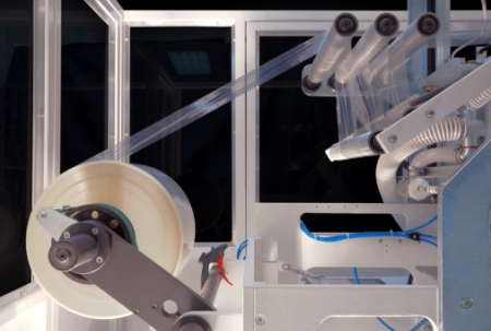
Etichettatrici
Modelli di encoder ad alta velocità e frequenza operativa per un controllo preciso ed efficiente di velocità e posizione.
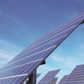
Energia solare
Linee di encoder magnetici estremamente robusti, studiati per controllare con precisione la posizione di Tilt e Azimuth negli inseguitori solari.
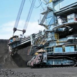
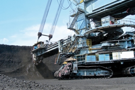
Macchine escavatrici
Soluzioni in acciaio INOX ad elevato grado IP, per garantire la massima resistenza del dispositivo in ambienti corrosivi e gravosi.
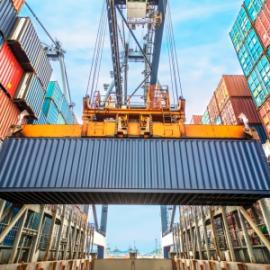
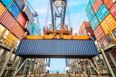
Sollevamento merci
Soluzioni adatte ad ambienti gravosi, estremamente robuste e resistenti alle vibrazioni provocate nel sollevamento di merci e materiali pesanti.
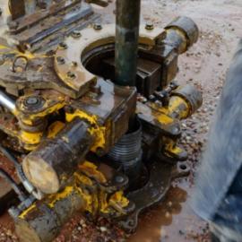
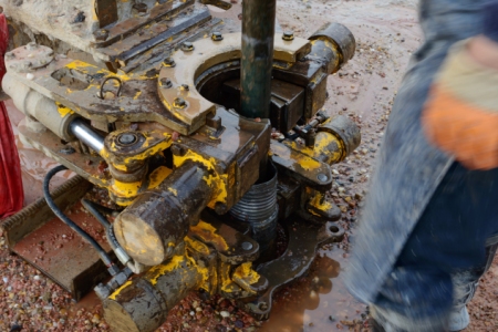
Argani e trivelle
Modelli robusti e resistenti, con certificazione ATEX, disponibili con diverse opzioni di interfaccia elettronica per un controllo preciso e sicuro di argani e trivelle.
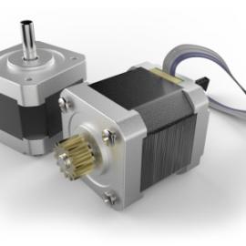
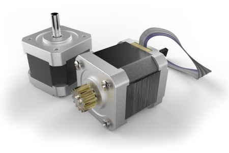
Motori passo-passo
Soluzioni di piccole dimensioni, facili da montare, studiate per essere altamente versatili e garantire la massima affidabilità.
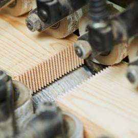
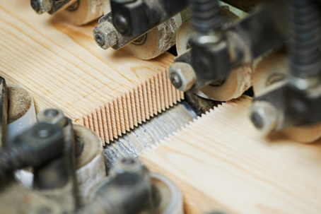
Lavorazione del legno
Dispositivi con ottima risoluzione e velocità operativa elevata, adatti all'applicazione su macchine da frese, presse e CNC (controllo numerico).
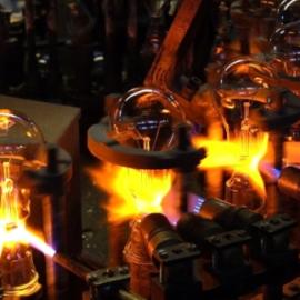
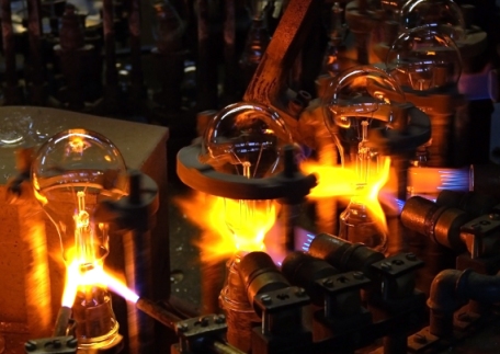
Vetro e ceramica
Dispositivi ad elevato grado IP, resistenti a liquidi e ad un ampio spettro di temperature, adatti alla lavorazione della ceramica e del vetro.
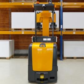
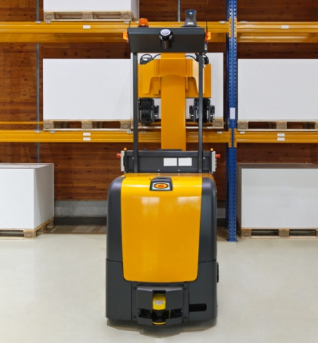
AGV (Automated Guided Vehicle)
Trasduttori rotativi e lineari a tecnologia magnetica, particolarmente compatti e ad elevato grado di protezione IP.
Plastica e gomma
Linee di encoder incrementali compatte e facili da montare, studiate per resistere ad un ampio spettro di temperature.
Paesi in cui siamo presenti
Part numbers
Utenti registrati
Ultime news
Alla radice di qualsiasi invenzione o innovazione tecnologica c'è sempre l'ingegno umano. Per questo siamo ben coscienti che sono le persone che compongono la nostra Azienda, con il loro know-how, le loro competenze ed esperienza a costituire il vero patrimonio di Eltra e a permetterle di crescere da oltre 30 anni.
"Think global, act local". Nel corso degli anni Eltra è diventata un'azienda con una presenza globale, con clienti in tutto il mondo e una rete di distribuzione che copre diversi continenti, mantenendo al tempo stesso la sua identità di industria Italiana, privilegiando sopra ogni cosa la qualità del prodotto e del servizio offerto al Cliente.
Per qualsiasi dubbio, richiesta di informazioni o chiarimenti su specifiche tecniche dei nostri encoder, potete contattare il nostro servizio di supporto al cliente via e-mail all'indirizzo:
support.eltra@broadcom.com
La nostra sede si trova a Sarego, loc. Monticello di Fara, a 26 Km dal capoluogo Vicenza e 40 Km da Verona.
Se ci raggiungete dall'autostrada l'uscita di Montebello dista a meno di 5 km, mentre il casello di Montecchio Maggiore si trova a circa 10 km di distanza.
Potete utilizzare queste coordinate sul navigatore:
Latitudine: 45.42167 - Longitudine: 11.39604.